This site is intended to be an ongoing report on progress, or lack thereof, in the design, construction and analysis of solar "cookers" or "ovens". The journey has been, and will continue to be, rather casual (to keep it enjoyable) and "peripatetic" (and hopefully not "peripathetic"). When this site was started (end of October, 2025), two sets of notes were posted summarizing progress, mostly mathematical in nature, that had been made over a period which began in the summer of 2024. These notes were written mostly for myself but they may be useful, or at least interesting, to others.
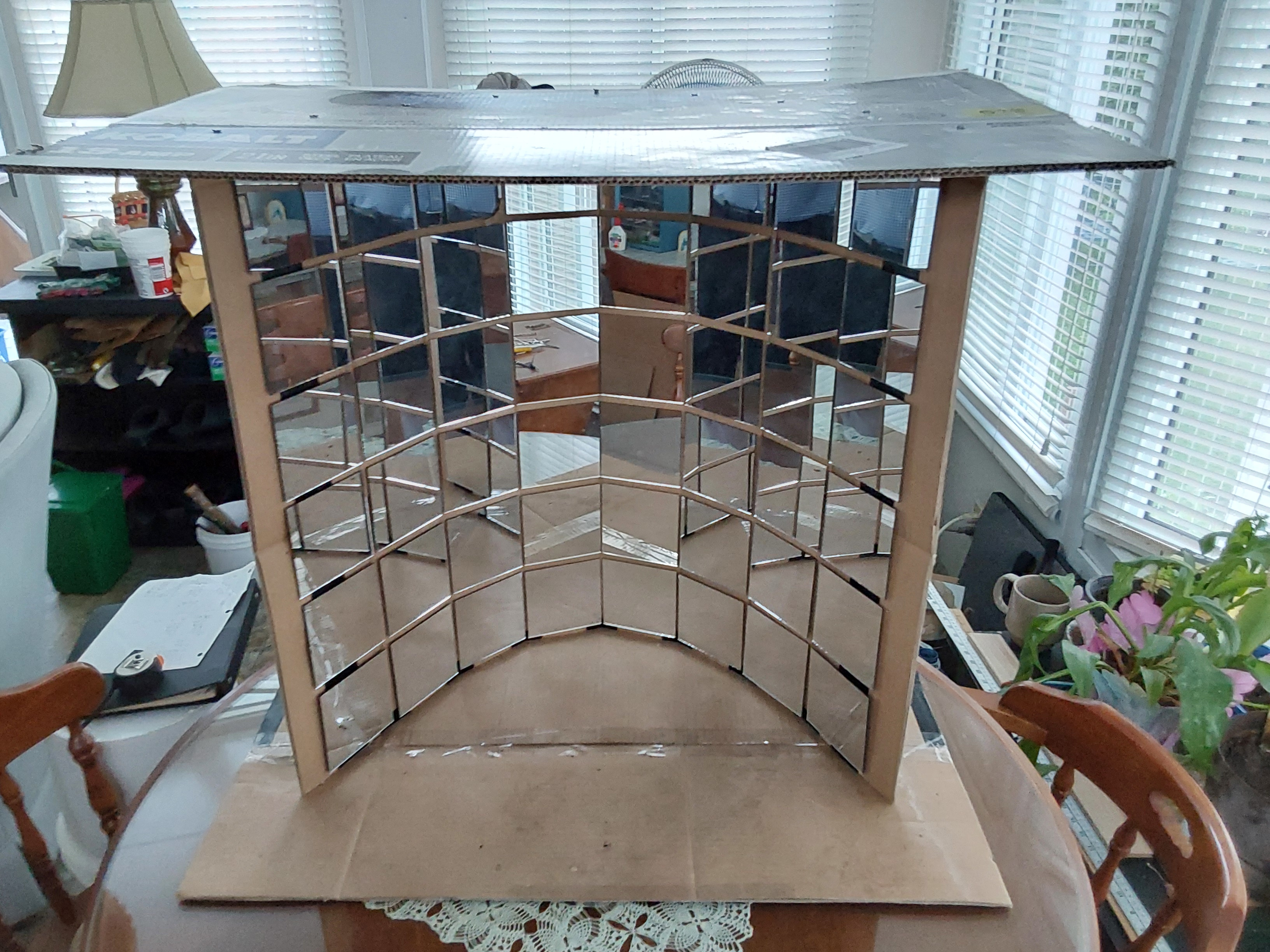
When I first thought about constructing solar cookers, my ideas – and, unfortunately, initial efforts – were rather grandiose. Here is a photo of my first construction, which might look like something from an old “Buck Rogers" space movie.
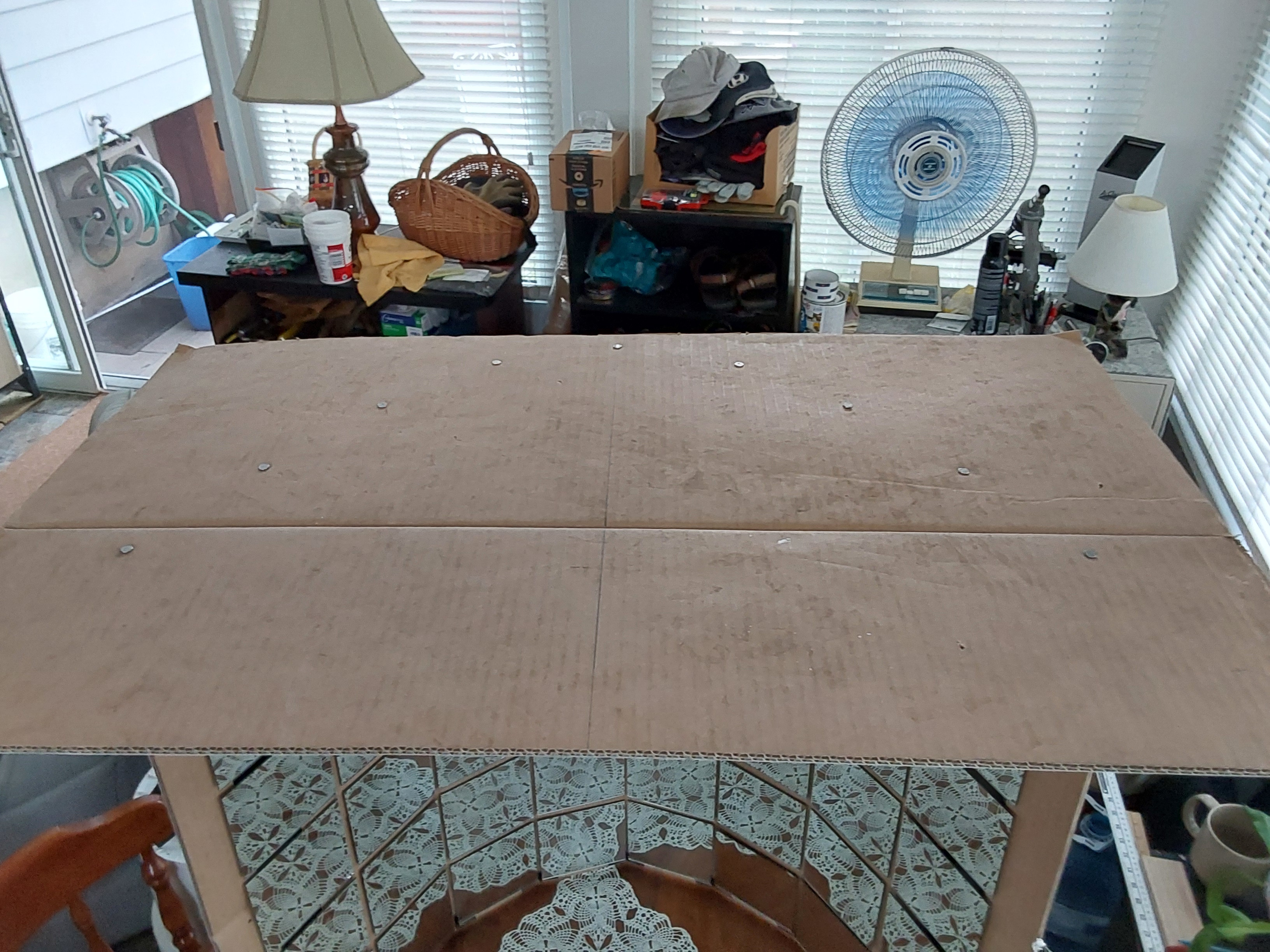
It is essentially a piecewise linear parabolic trough constructed from 4” X 4” mirrors (purchased from Amazon). Here is a top view of the above solar cooker: If you look closely, you should be able to see the heads of nails which fasten the top (and the base) to the corrugated cardboard on which the mirrors are glued – the nails lie on the curve y = x2. More precisely, the nails lie at the points between contiguous mirrors, the endpoints of which lie on the curve. The 4" x 4" mirrors were spaced 0.25" from each other (to allow necessary bending of the cardboard to create the parabolic shape), so the nails lie 4.25" apart.
The 4” X 4” mirrors, therefore, comprise a piecewise linear approximation of a parabola which is translated in the z-direction to produce a (piecewise linear) parabolic trough. In order to get an idea of the distribution of reflected rays – which will clearly be a perturbation from the line of focal points for an ideal (i.e., continuous) parabolic trough – one would have to examine the distribution of reflected rays for piecewise linear approximations of a parabola. But in order to attack this problem, it was necessary to consider first the more general problem of finding (i) the y-intercepts of (initially downward travelling) light rays reflected from a reflective surface having the form y=f(x) and (ii) the distribution of these intercepts along the y-axis. All of this preparatory work led to the following set of notes:
I. Determining the distributions of reflected rays for a general class of curved mirror surfaces
The results from this first set of notes (there is some interesting mathematics to be found here) were then used to compute distributions of reflected rays (along the y-axis) for piecewise linear approximations to curves in the plane. These results are presented in the following set of notes:
II. Using small mirrors to construct piecewise linear mirror surfaces for solar cookers
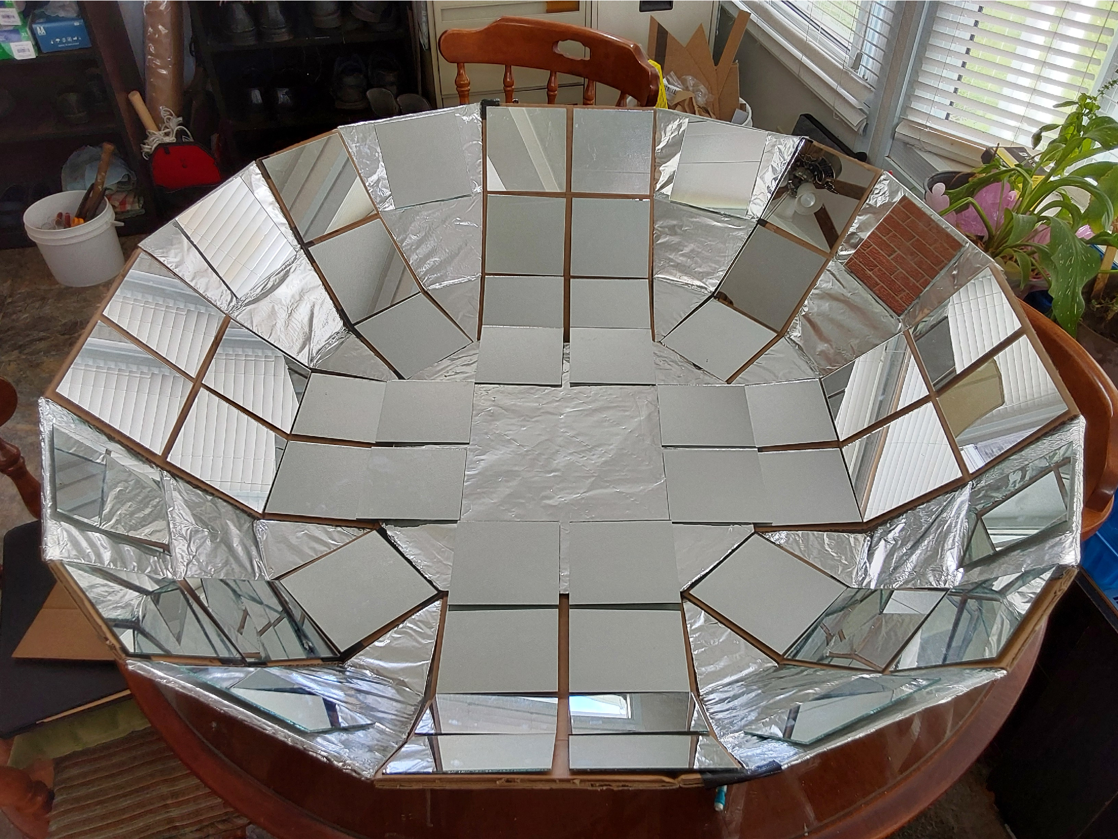
I then decided that a 2D parabolic trough would perform a better concentration of reflected rays. Here is a photo of my second construction - “Star Wars” anyone?
The thought of constructing something to hold a pot that would lie in the region of concentration of reflected rays seemed rather daunting so I decided to change direction. I began searching YouTube (better late than never) to see what people were doing and found a plethora of videos which described the construction of much more effective – and smaller! - solar cookers. Many of these cookers are essentially “solar ovens” where light from the sun is focused into an almost entirely insulated “oven” (one side is transparent – usually in the form of plate glass - in order to let the light into the oven). Temperatures in these ovens can reach 300 degrees Fahrenheit and beyond.
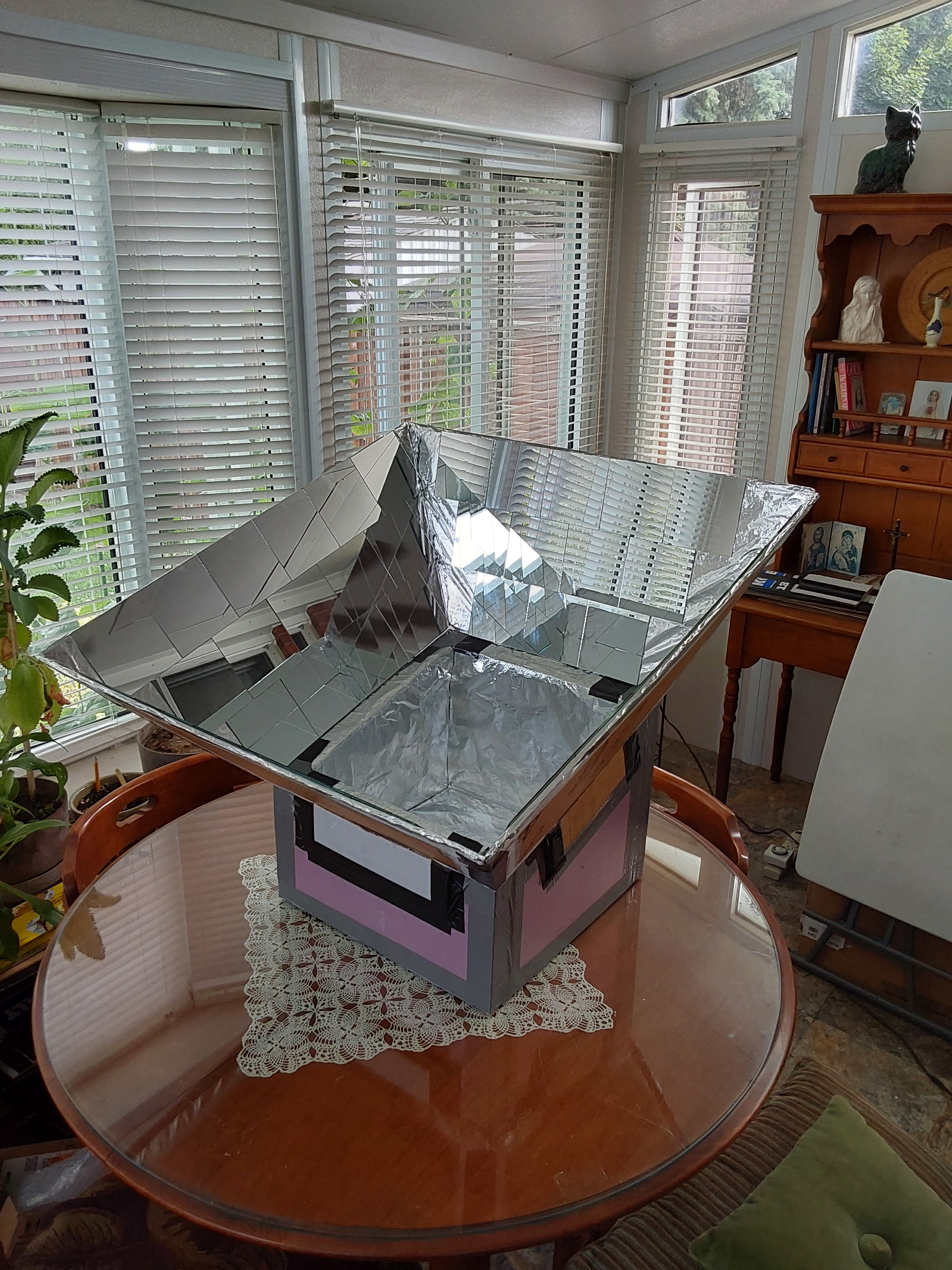
Here is a photo of my first such “solar oven” (June 1, 2024).
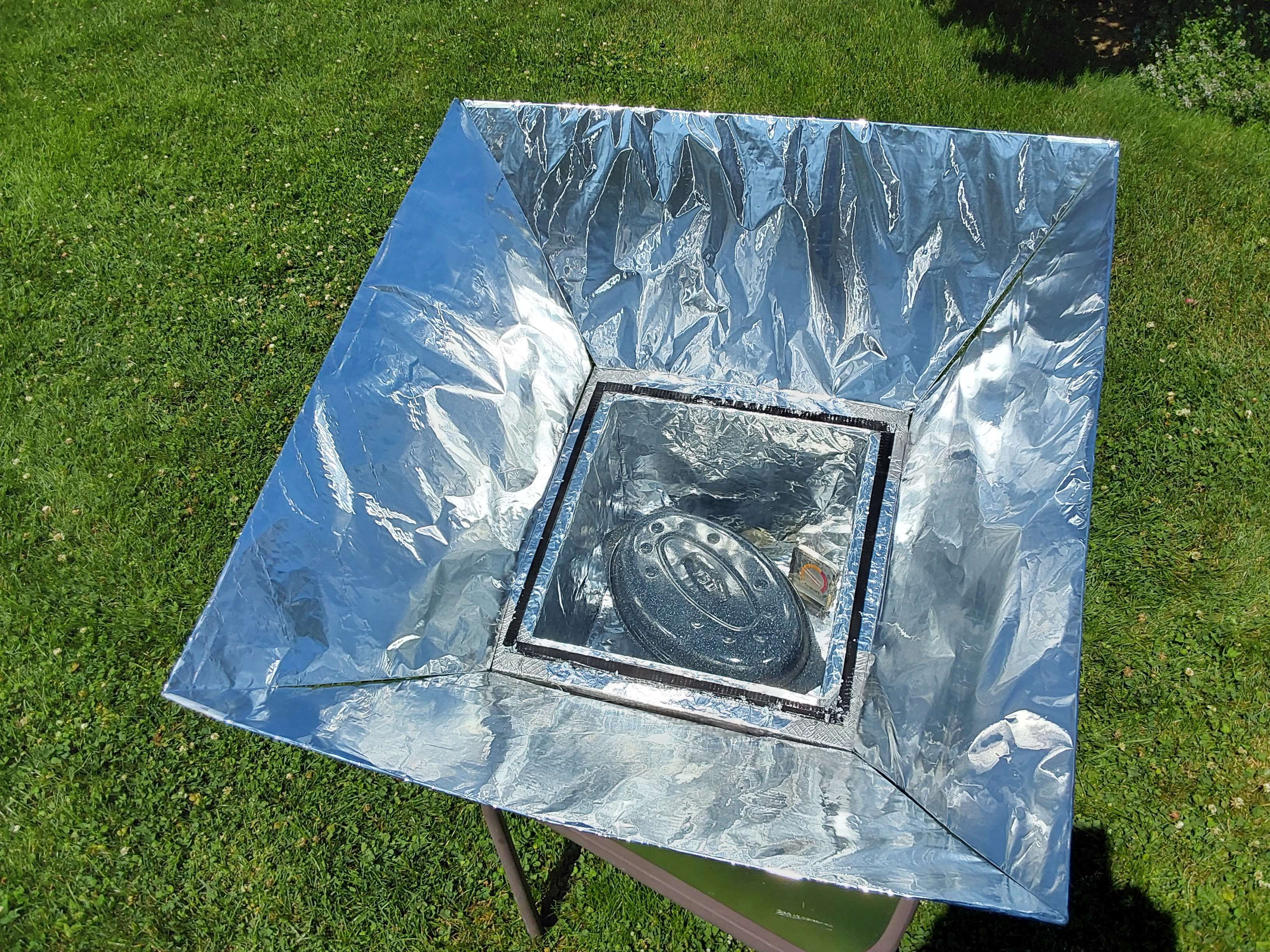
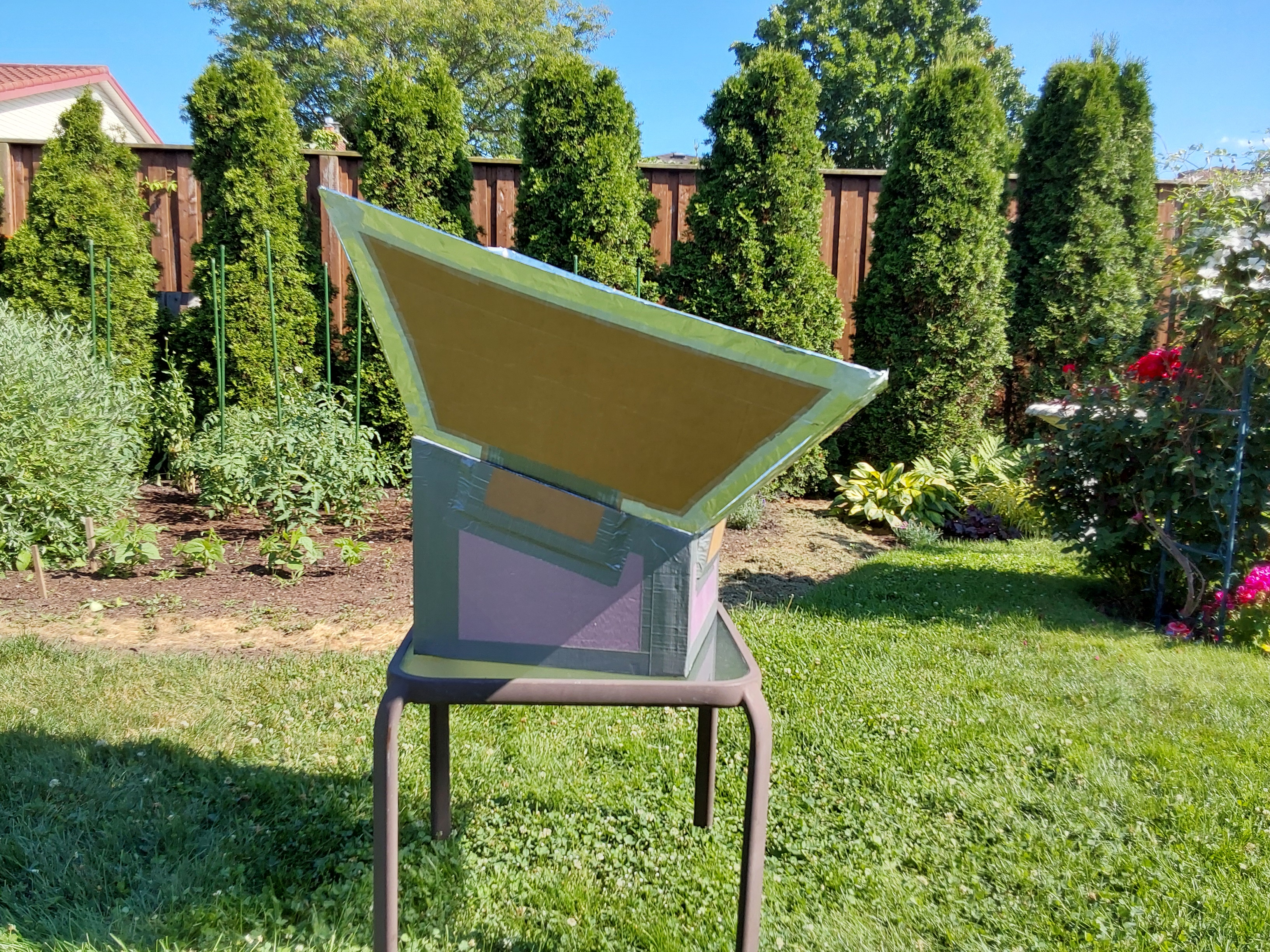
The dimensions of the oven are 15" x 15" (base length and width), 7" high at the front, 11" high at the back. The sides and bottom of the oven were made from leftover rigid foam insulation board with thickness 1.5" (R 7.5 value, I believe) and attached to each other with 2 1/2" screws followed by duct tape. These dimensions were chosen to produce an oven interior of dimensions 12" x 12". The top of the oven is covered with a 13" x 13" glass plate (simple 3 mm glass used in old windows) - the edges of this plate were covered with Gorilla tape for handling. (Handles were added later.) The reflective sides or "wings" were constructed from cardboard and covered with “no-name” heavy-duty aluminum foil (shiny side out), as are many of the solar ovens you find on YouTube. Each of the four sides is one foot in height and oriented at a 30 degree angle from the normal to the oven top. In this way, light from the sun is reflected – at least theoretically and when the sun is directly above the oven top – over the entire width of the oven top. As I discuss in Paper I, the sizes and angles of inclination were chosen as a kind of compromise between several competing factors, i.e., (1) making the area of captured sunlight large but (2) using as little material as possible to make the sides. The need for the “tilt” in the inclination of the oven top, hence the reflective sides, should be obvious – the closer the sun is to the normal of the oven top, the more direct the incoming sunlight. (More on this later.) The four reflective sides were taped to each other but not to the oven. Each side had a downward pointing tab that was to be inserted into a slit located beside the oven top – in this way the sides could be somewhat secured into the oven base.
The interior of the oven is simply coated with aluminum foil. There are many variations – and corresponding justifications - to be found “out there”, e.g., aluminum foil, dark paint. I chose aluminum foil because of its simplicity and with the idea that light reflected internally could possibly heat the cooking pot directly as opposed to the oven wall.
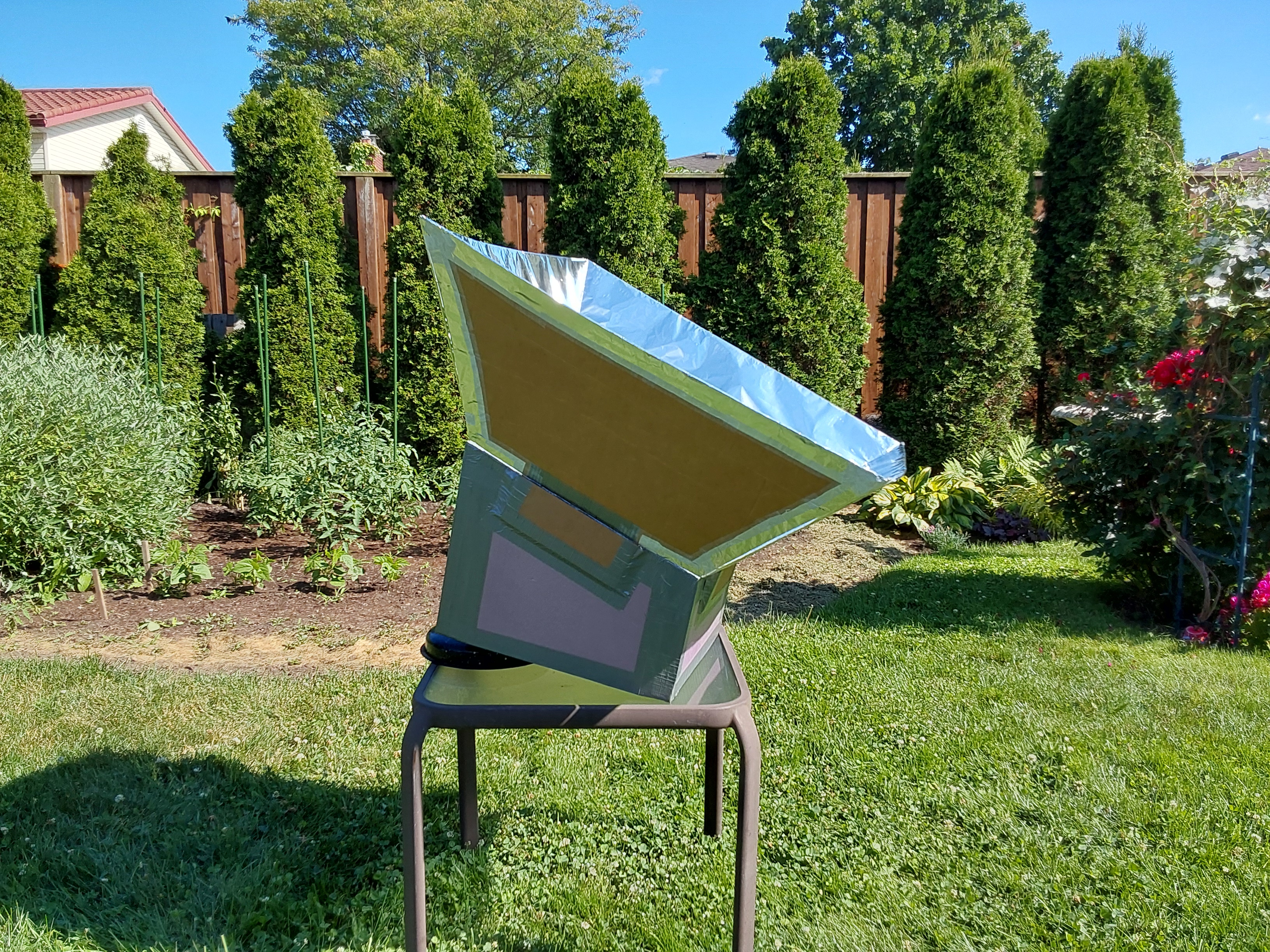
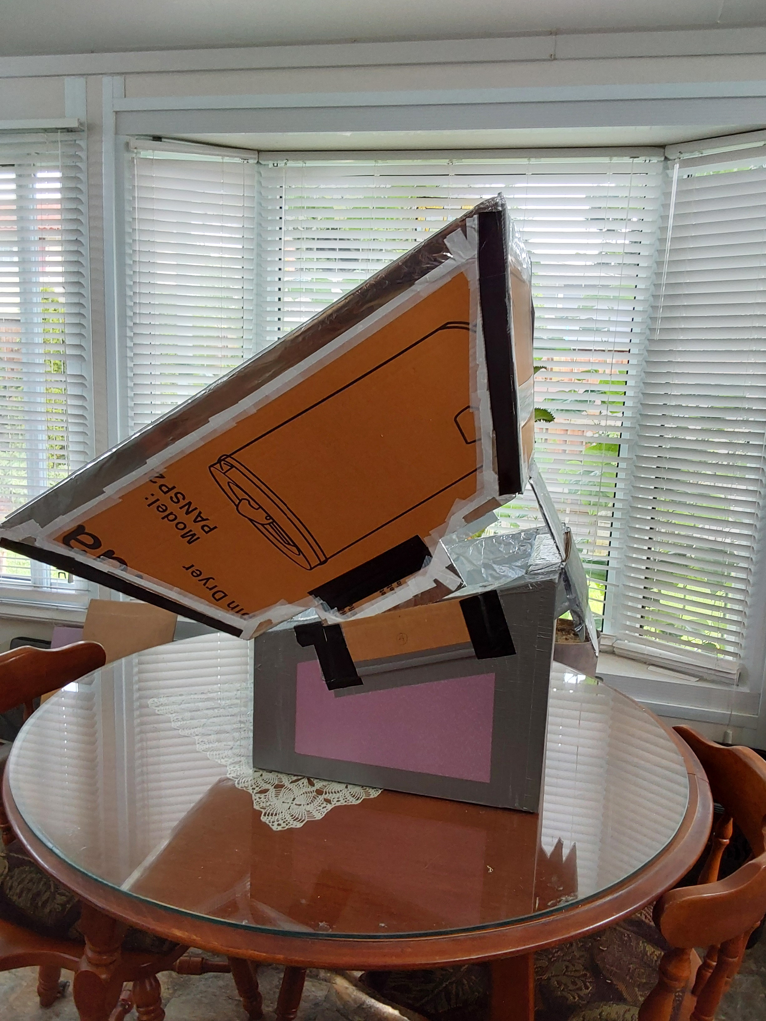
With this oven temperatures of 250-300 degrees Fahrenheit, and even higher, could be achieved during the month of June, especially if the entire cooker was additionally tilted to allow more direct sunlight entry, e.g.,
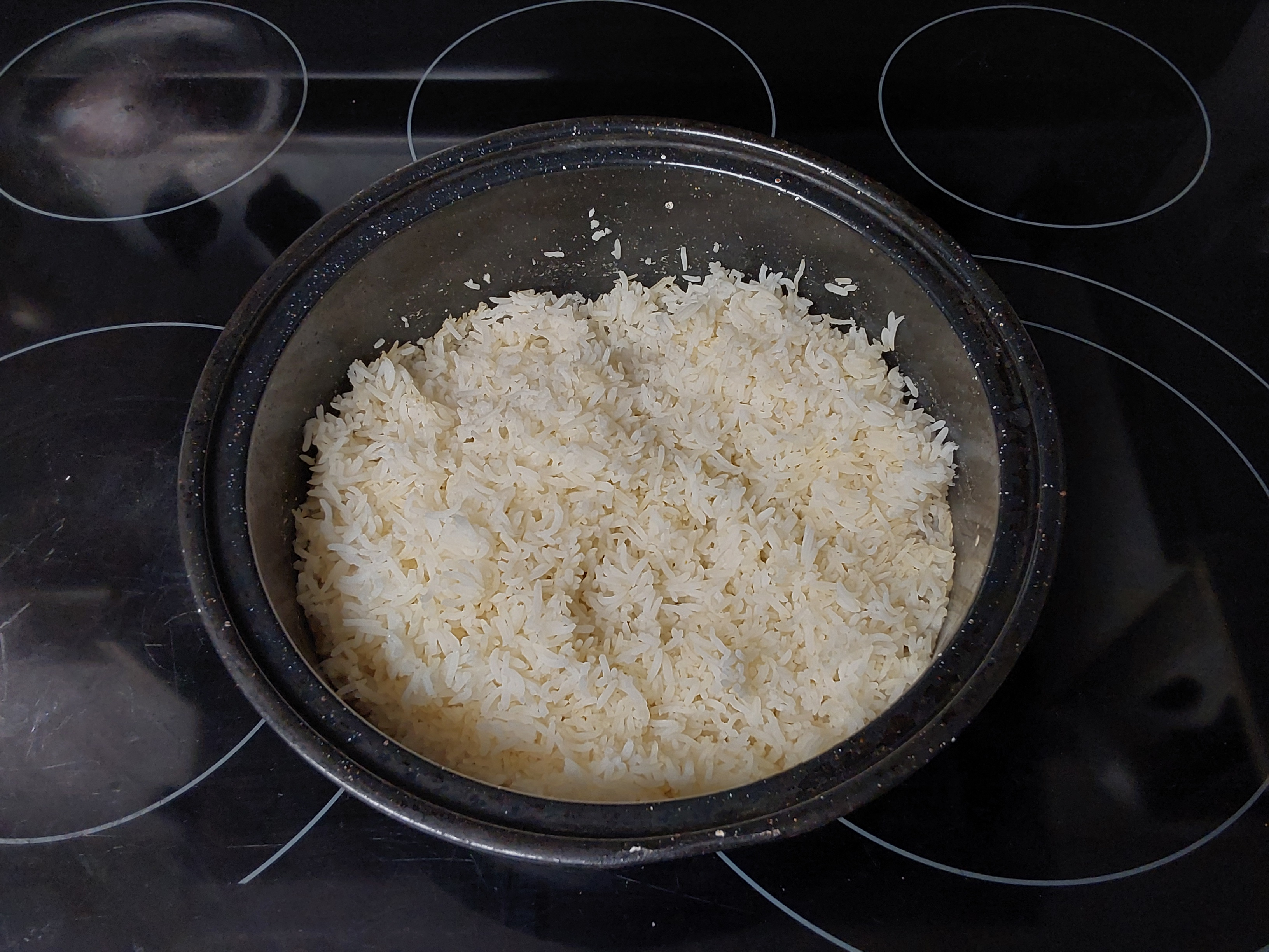
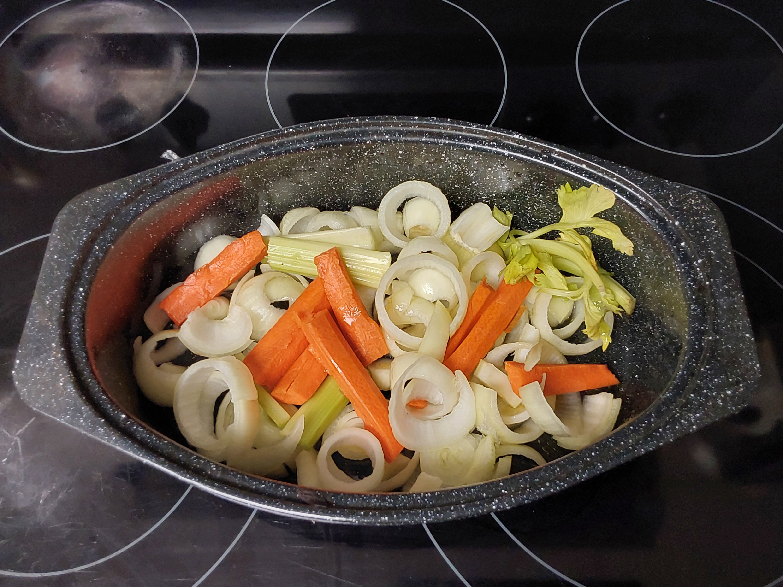
As well, it was necessary to rotate the cooker occasionally in order to follow the sun. Here are some samples of food cooked in the oven. (I have not tried to cook meat in it.)
Given how well this version of the solar oven was working, and the fact that I already had a stack of 4" x 4" mirrors that were used for my “Star Wars” project, I decided to attach the mirrors to the sides in order to increase the reflectivity. The result is shown in the photo below (July 3, 2024).
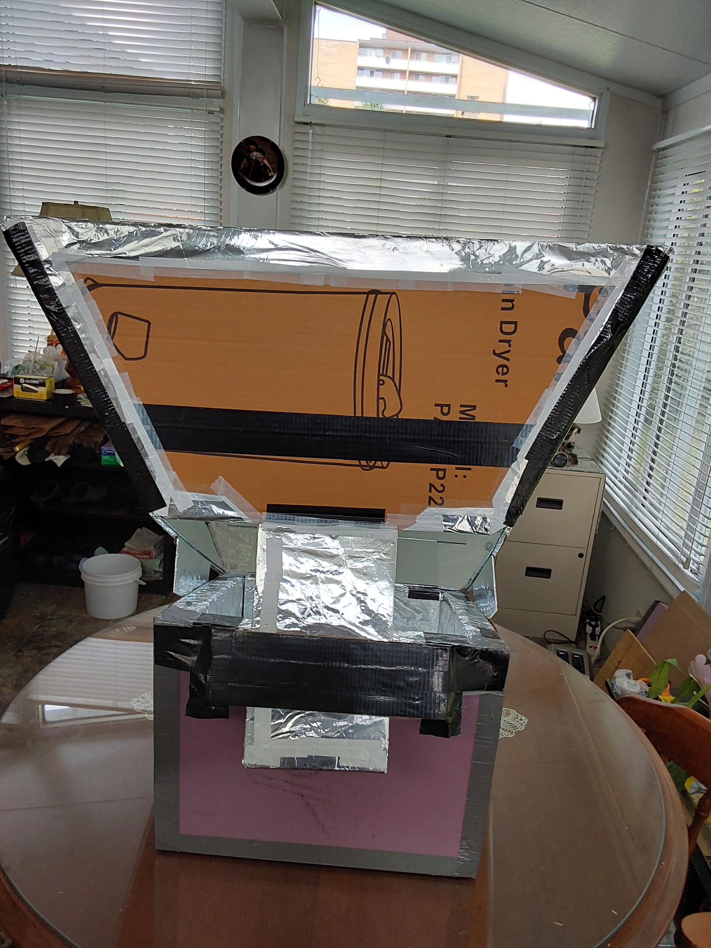
The increased reflectivity of the mirrors made it possible for higher internal oven temperatures to be achieved – on the order of 300-350 degrees Fahrenheit. The tilting tab allowed the oven to be functional during later hours of the day when the sun was lower in the sky. Admittedly, this tab is rather crude and some improvement is necessary - and planned.
This solar oven has served me well for over a year. I should mention that after using it, I have always (correction - almost always) brought the oven indoors before nighttime - except one time, when I forgot about it and left it outdoors overnight. Unfortunately, that late summer night was exceptionally humid with much dewfall. This warped the cardboard sides significantly (what an ugly sight – I’m glad that I didn’t take photos) and weakened all the (Gorilla) tape connections. There were two choices: (1) the scrapyard or (2) some kind of repair. I chose (2) by constructing new cardboard sides - the only cardboard on hand was thinner so I decided to reinforce them by attaching horizontal strips of old hardwood flooring. Instead of using tape, I "sewed" neighbouring sides to each other using metal wire. The result - almost as good as new. That being said, I have been thinking of constructing another oven which will be quite similar to this one, perhaps with an increased tilt angle for the top of the oven and a more secure method of tilting the reflective side assembly above the oven.
Dated October 30, 2025